Would you like to learn how to create your own automated shades for a fraction of the cost of buying them? In this blog, I will walk you through how I created my own blackout shades for my home theater.
More...
Materials
Blinds
Use the blinds.com instructions for measuring and ordering your blackout blinds.
You won't be using anything that comes with the blinds, except for the blind material itself.
The blinds come rolled up on a cardboard tube. Unroll the blind material and detach it by starting on one side and carefully tearing it off from the tube.
You will need to clean all of the glue off from the blind material that you can. Don't worry if there is still a little glue residue left on the material like in the picture below. It shouldn't affect anything.
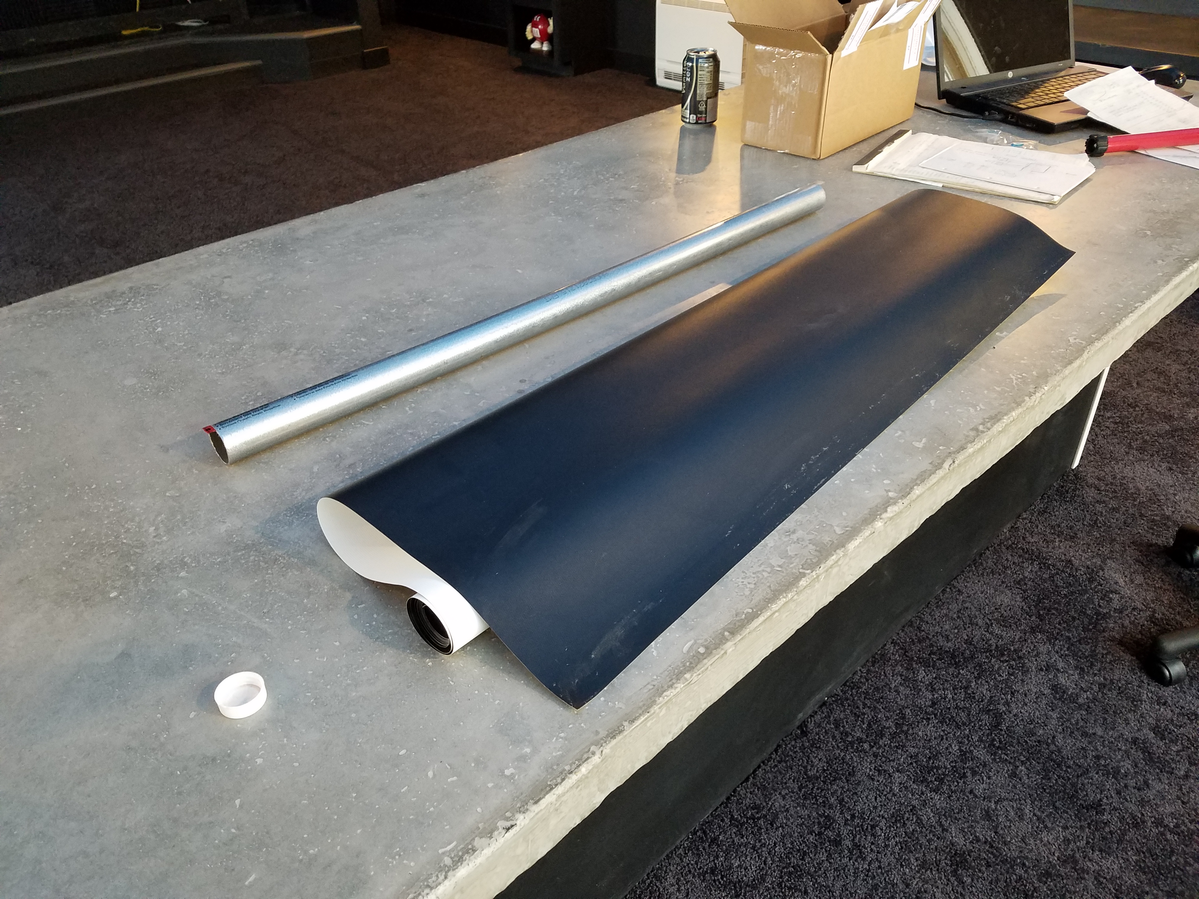
Blind Material
The Pipe
Next, cut the 1-1/4" EMT pipe, so that it is the same length as the blind material. You can use a hacksaw for this.
Then, draw a straight line across the pipe. TIP: To draw a straight line across the length of the pipe, place it into a spare piece of the corner trim and use the trim as a straight edge.
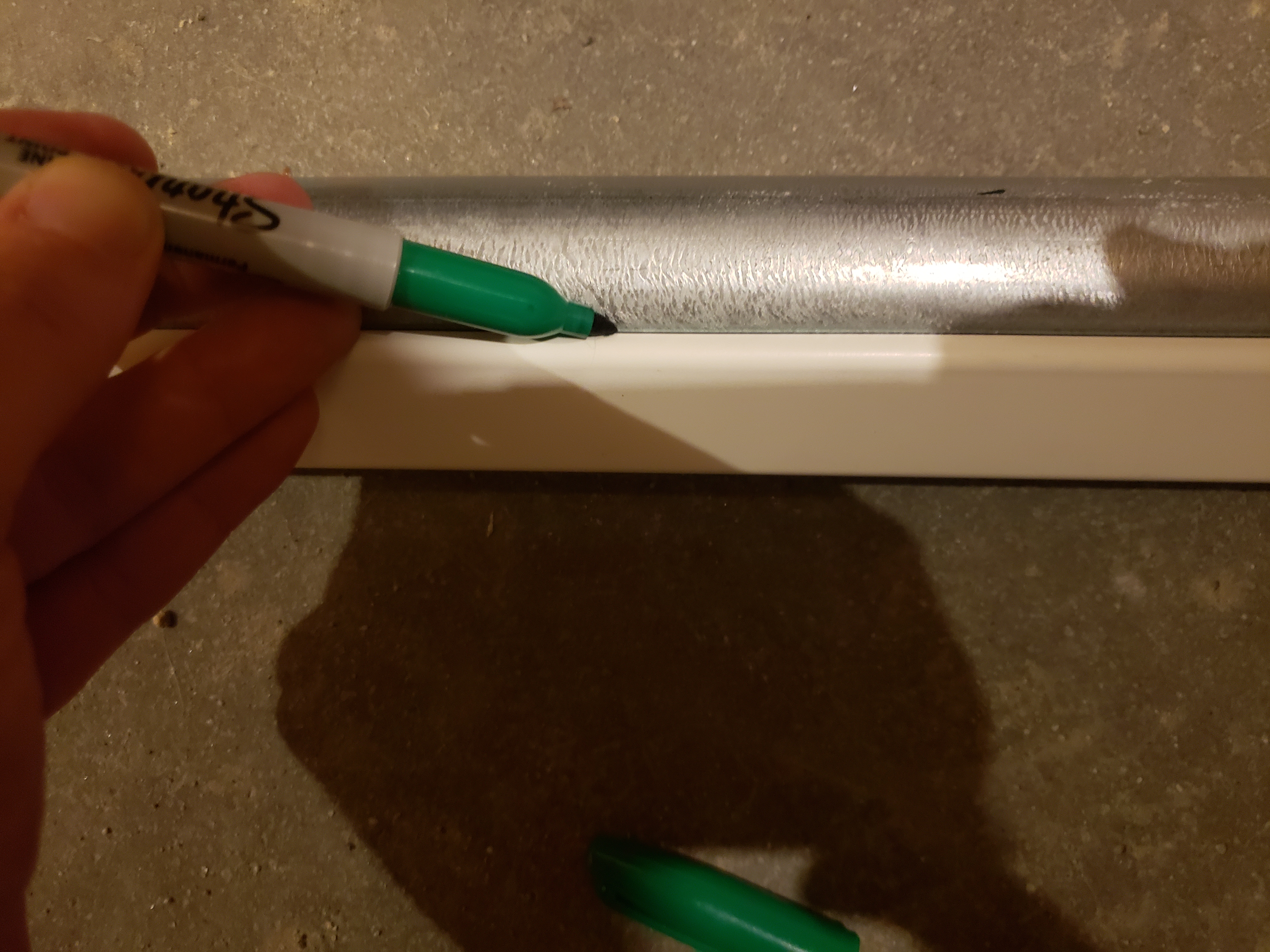
Marking The Pipe
Using the line as a guide, run a piece of double sided tape across the length of the pipe.
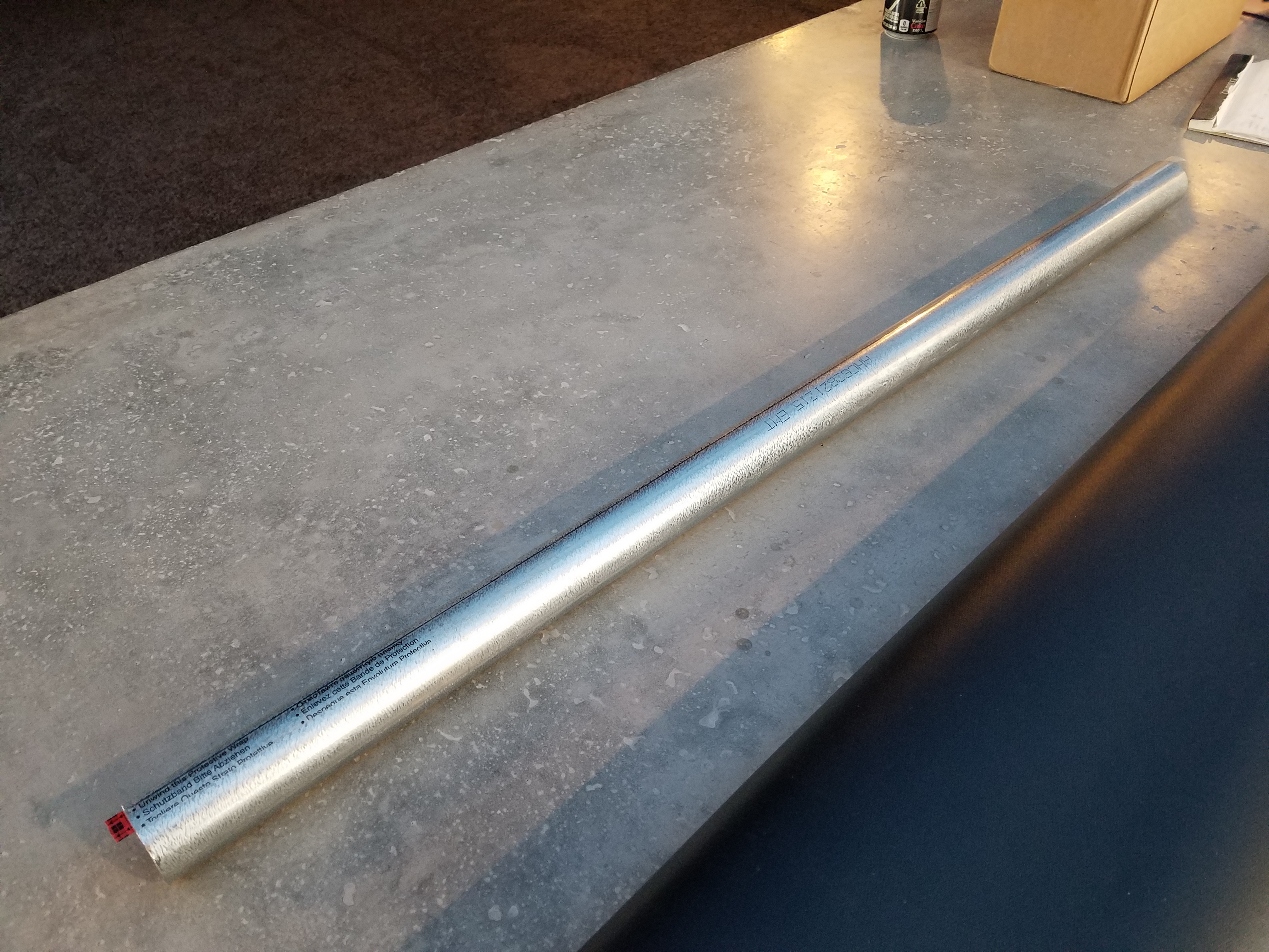
Pipe
Attaching the Blind to the Pipe
Remove the protective cover off from the double sided tape.
Using the line you drew on the pipe in the previous step, start on one side and carefully attach the black side of the blind material to the pipe by pressing the edge of the material down onto the tape.
Once the material is attached to the pipe, slowly roll it up so that the black is on the inside and the white is on the outside. Make sure it is rolling up evenly as you go.
Inserting the motor
The motor should slide into the end of the 1-1/4" EMT. Carefully slide it in as shown in the images below. Be sure to put it into the end that will be facing the side of the window that has the wires.
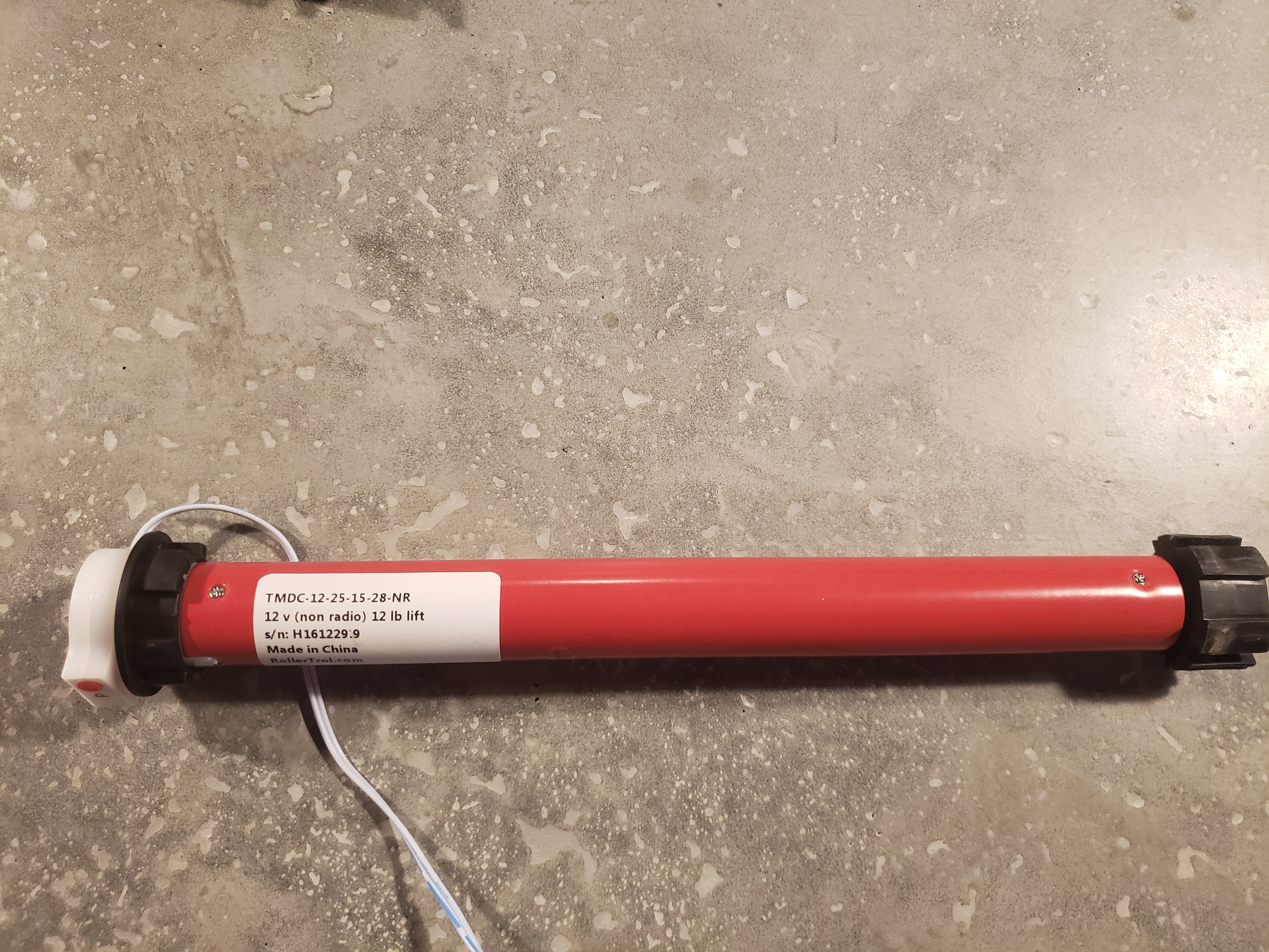
Tubular Motor
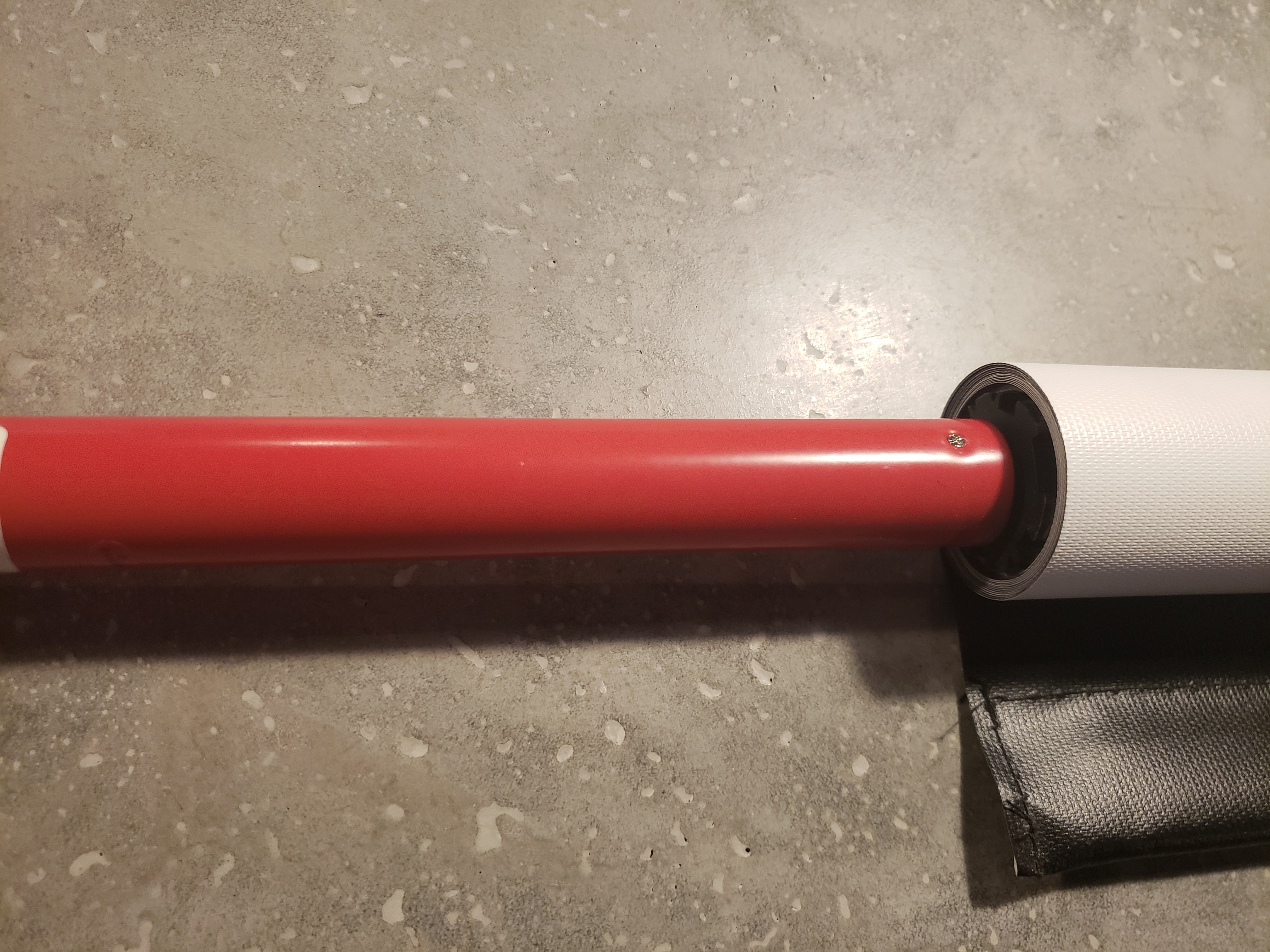
Insert End Into Pipe
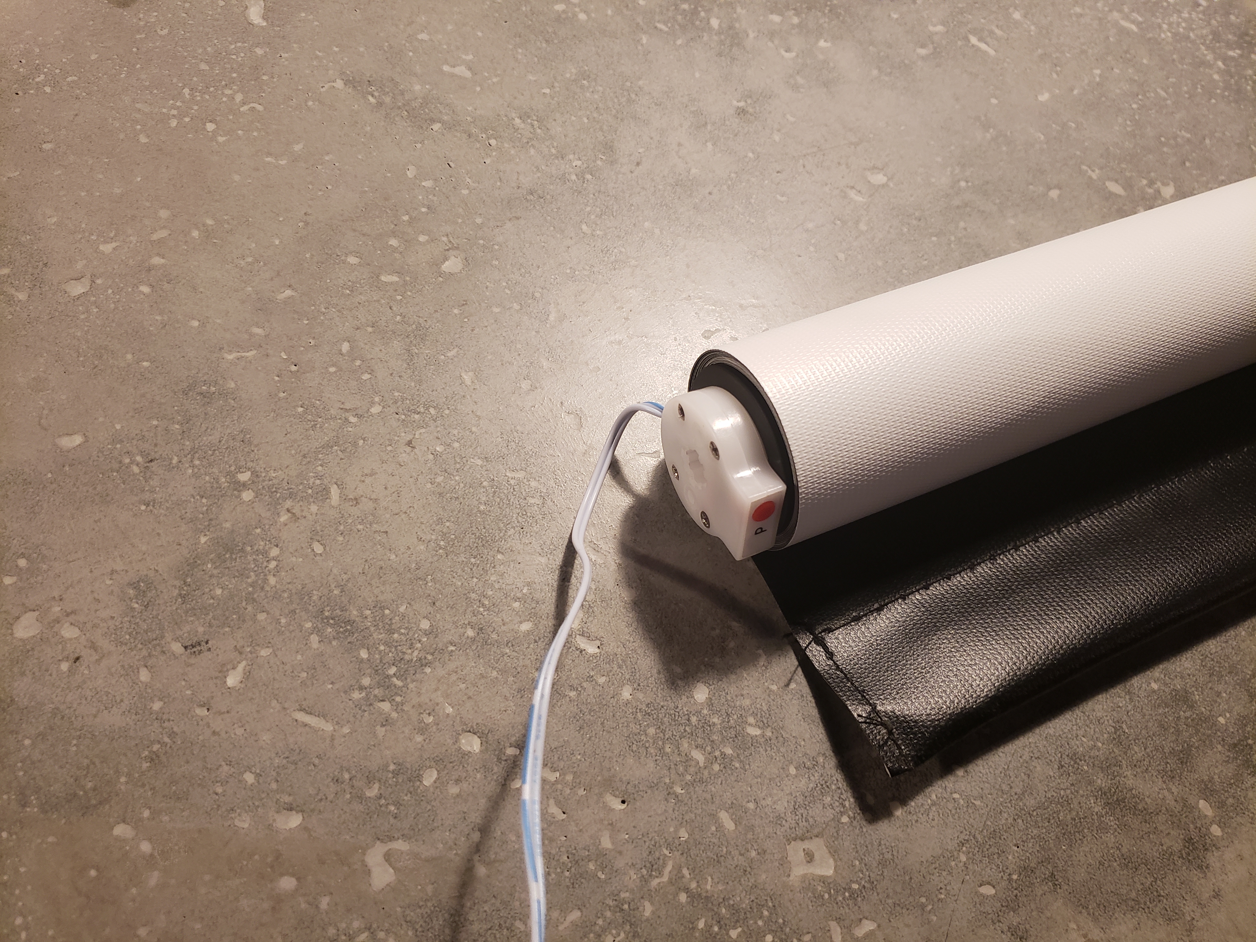
Tubular Motor Inserted Into Pipe
Now insert the idler end cap into the other end of the pipe.
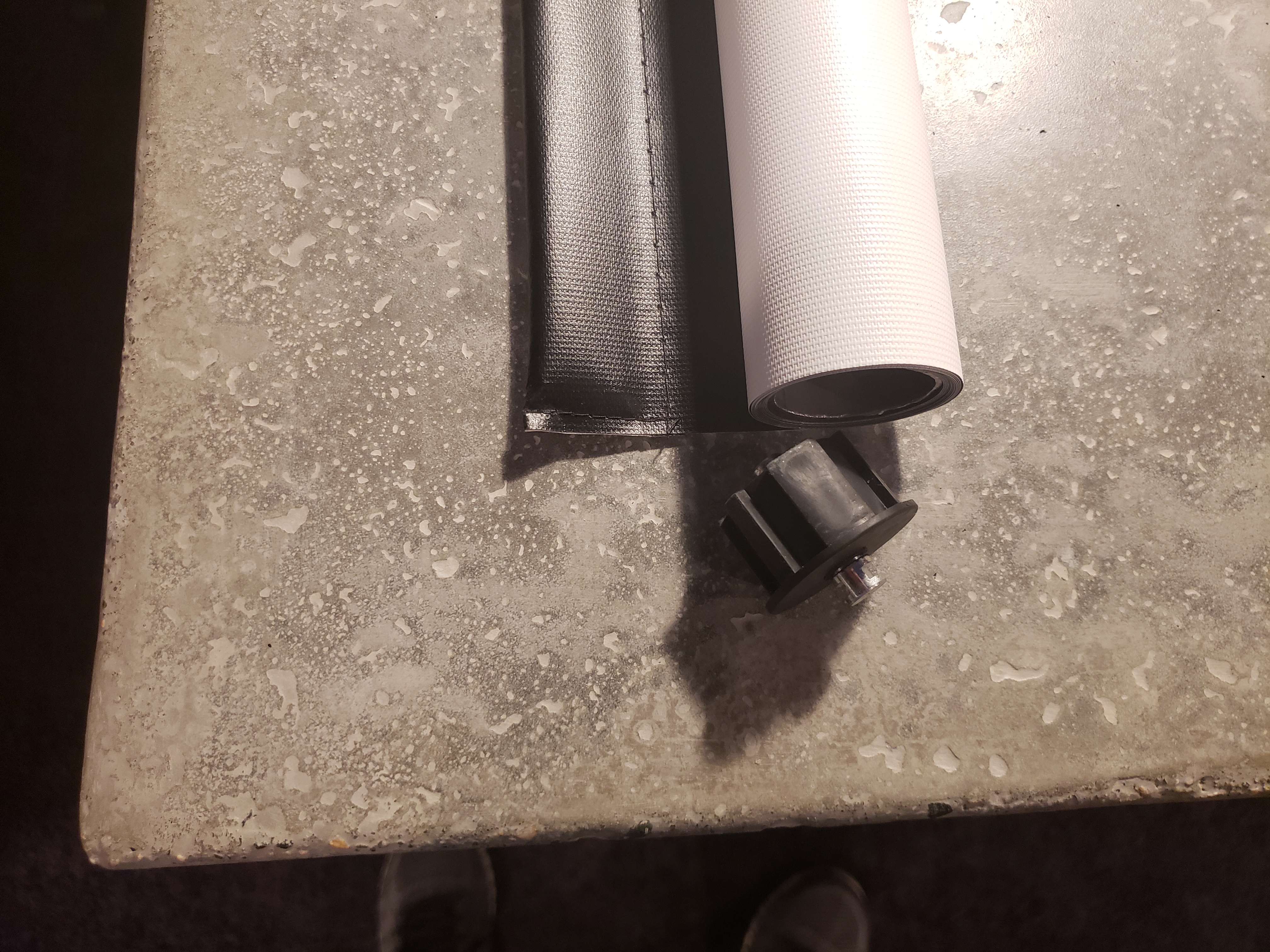
End Cap
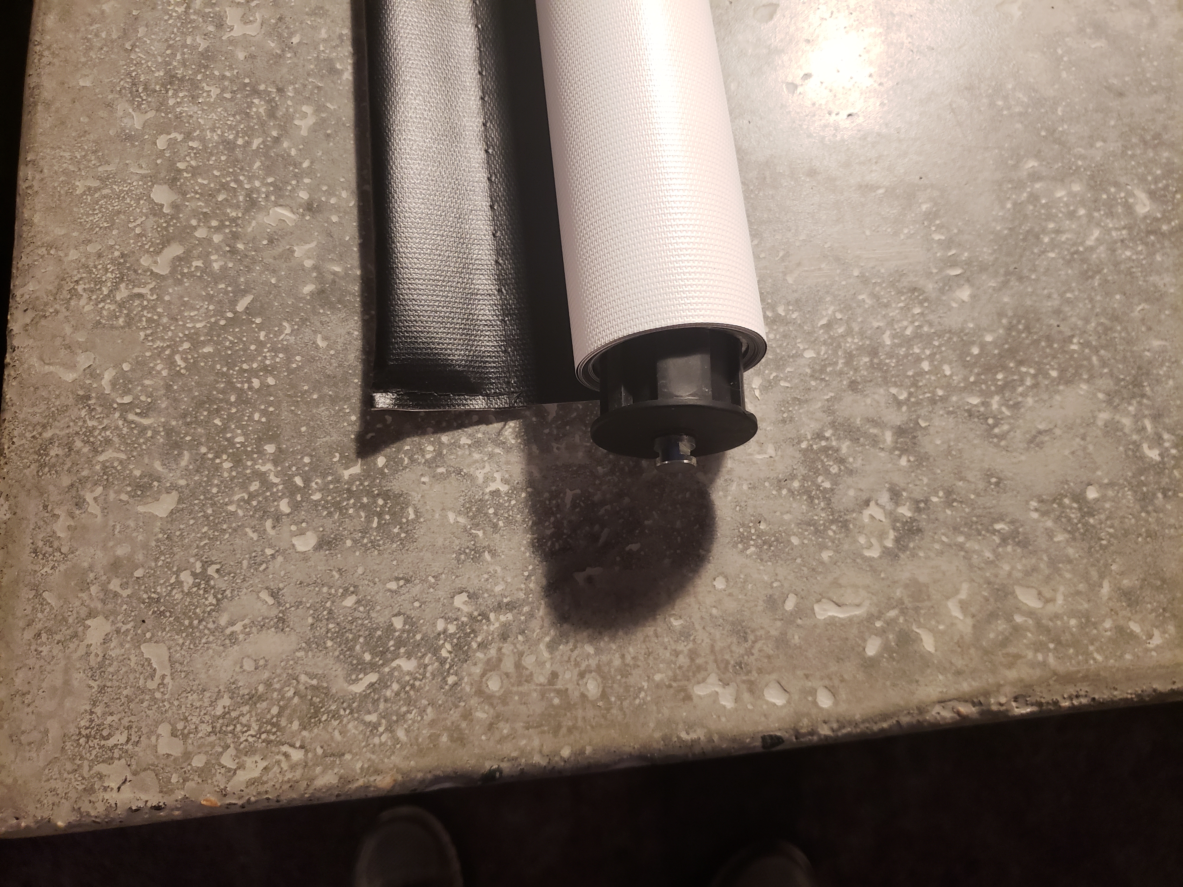
End Cap Being Inserted
The Brackets
The motor side bracket has a tab that sticks out that will insert into the motor.
The end cap side bracket has a slot that the end cap slides down into.
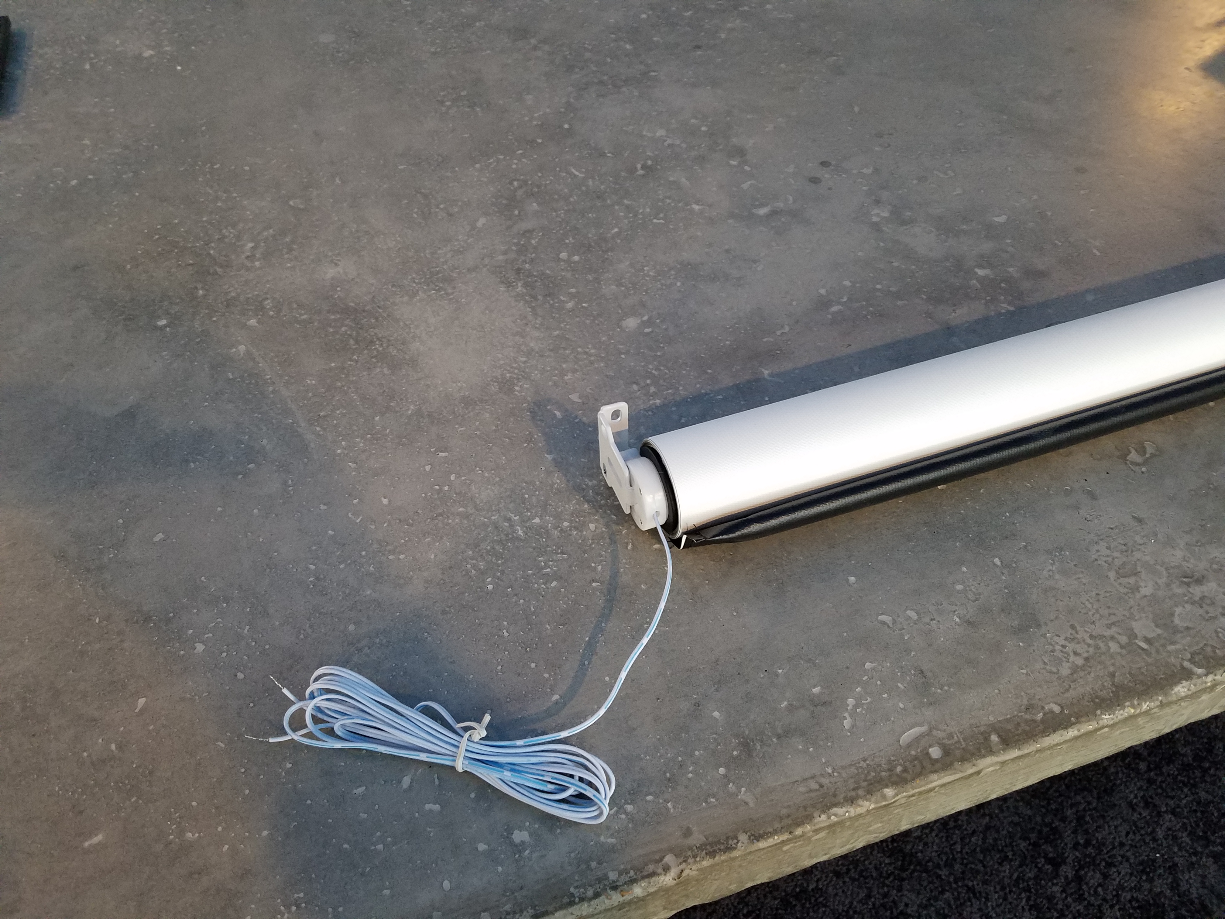
Motor Side Bracket
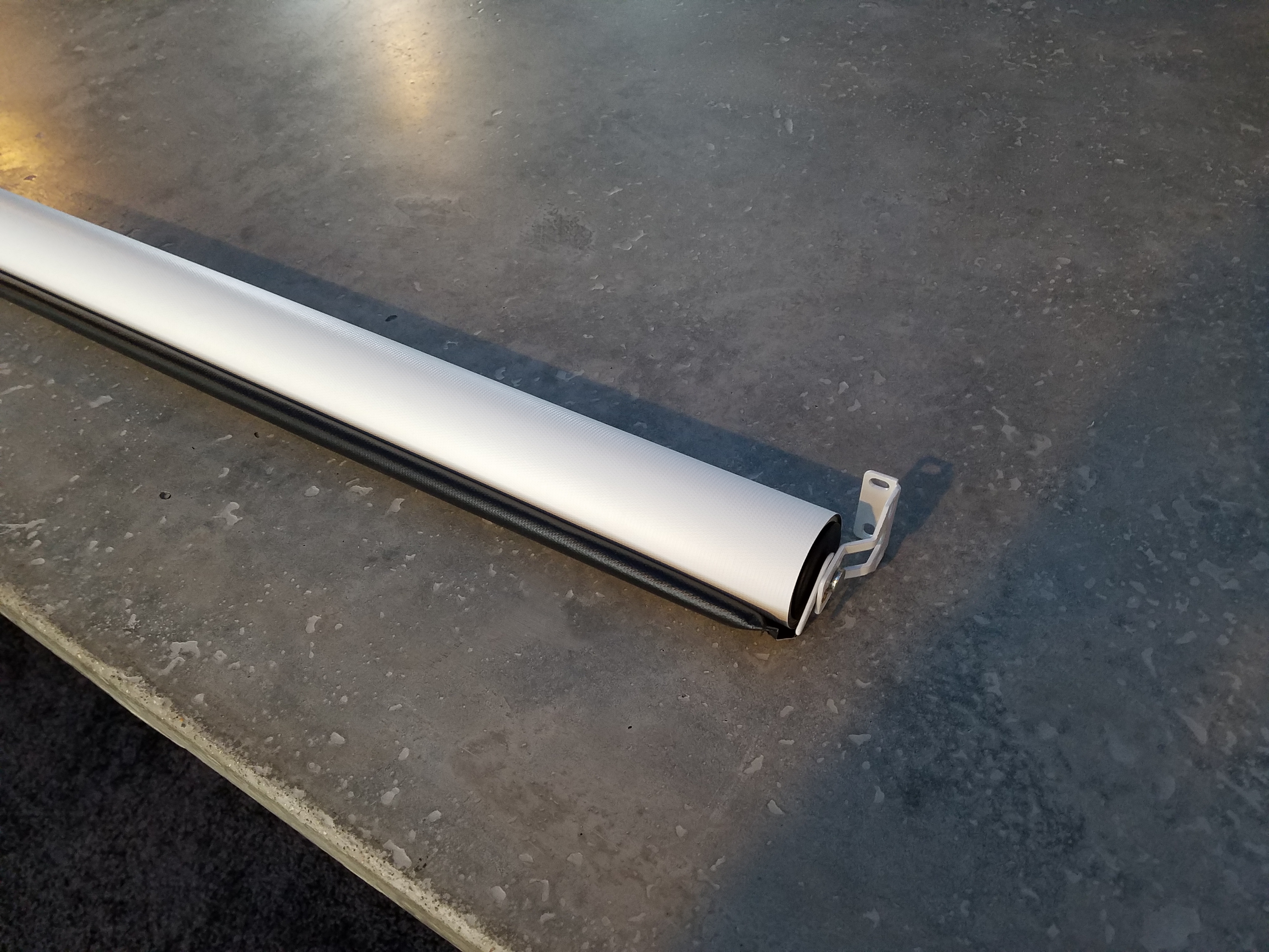
End Cap Side Bracket
Mounting
Hold the blind with the brackets in it up to the top of the window and mark the holes with a pencil.
Take the brackets off and using small wood screws, mount them to the window using your pencil marks as guides.
Now mount the blind by putting the motor side in first and then dropping the end cap down into the slot on the end cap bracket.
See Rollertrols Instructions here!
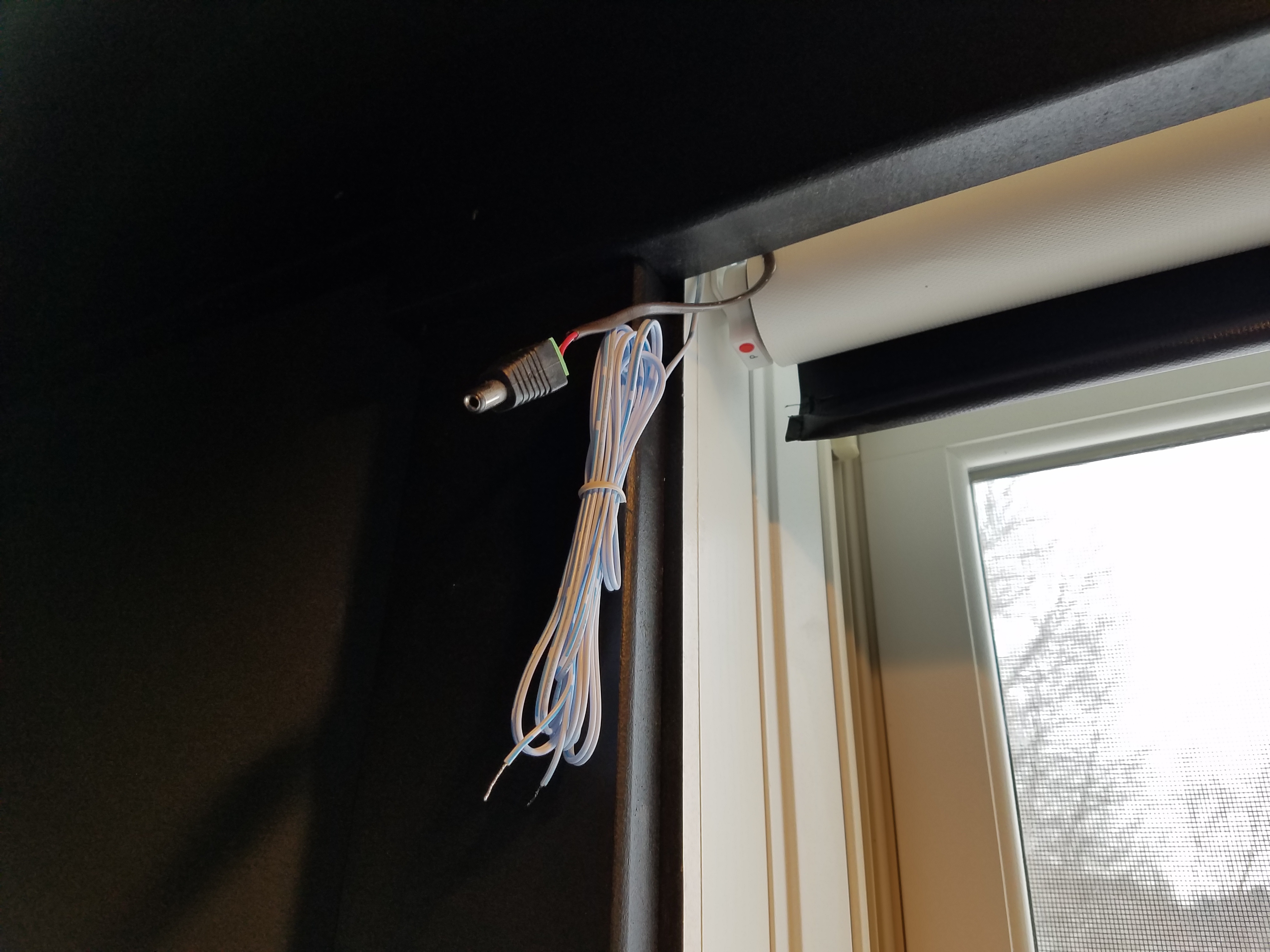
Blind Hanging
Programming the Motors
You need to set the upper and lower travel limits on the motors, so that they roll and unroll to the proper locations. Use the 1 channel wall controller, and the power supply to set the limits on each motor before permanently wiring anything.
These instructions can be found on Rollertrols site here. For your convenience I have copied them below:
The travel limits of these RollerTrol™ motors can be set and changed at any time . The sequence is as follows:
Activating the Programming Mode:
- Activate the motor in either direction with the UP or DOWN button of a switch or controller; we'll assume for these instructions that you will start with the UP button.
- While power is applied (the motor may not be running, if it has reached a travel limit), insert a screwdriver in the programming hole described in step 1 and hold the setting button down within six seconds of the power application start time. If you don't do it within 6 seconds, remove power, then re-apply power again (you'll have another 6 seconds to do it). Continue holding the setting button down until you hear a quick sequence of short beeps, then release the button. If the motor is running, it will stop, even though you are still applying power. REMOVE POWER FROM MOTOR.
- At this point, the motor has entered into its limit programming mode. Even though you have removed power, it will remember that it is in programming mode. You must complete the programming sequence or it will be permanently in programming mode.
- Apply power again for the UP direction, and it will continue running in that direction. Let it run until you are close to the desired UP position, then STOP it (do not let it go past the desired UPPER limit).
Setting the UPPER Limit:
- At this point of the programming mode, and you have moved the motor so that it is close to the UPPER position limit (but not past). When you stopped it, you removed power from the motor, but it has an internal memory that 'remembers' that it is in settings mode. Activate the UP direction of the motor; the motor now enters the 'JOG' mode. You'll see the motor move in very short steps that are a small fraction of a full rotation. Alternate between UP and STOP modes until your motor is at the exact UPPER limit you desire.
- The UPPER limit has been reached at this point, and the motor is still in 'programming mode', even though it is stopped without any power applied. The next step will be to press the DOWN button, which will set the UPPER limit into memory (you'll hear a confirming beep sequence), and it will also start the shade moving in the opposite direction. Do not press STOP until it gets close (but not past) the LOWER travel limit.
Setting the LOWER Limit:
- At this point you have stopped the motor, ready to enter JOG mode. Press the DOWN button and you will see it move slightly; you are now in JOG mode.
- Alternate between DOWN and STOP modes until your motor is at the exact LOWER limit you desire. Make sure it is stopped, with no power applied when you reach the desired LOWER limit.
- To confirm the LOWER setting and exit the programming mode, press the UP button; you will hear a beep sequence. At this point, the travel limits for the motor have been set and the motor is now back in normal running mode and you should be able to test the full excursion. Repeat the above steps if you need to reset the travel limits.
We sincerely hope you enjoy using these advanced motors; if you have any questions, please feel free to contact usat any time!
Trim
To prevent light from coming from around the blind, I used 1-1/8" PVC corner molding to create a small picture frame around the window. This helps block light from coming through from around the blind. Make sure you stop short from the blind as shown in the pictures below.
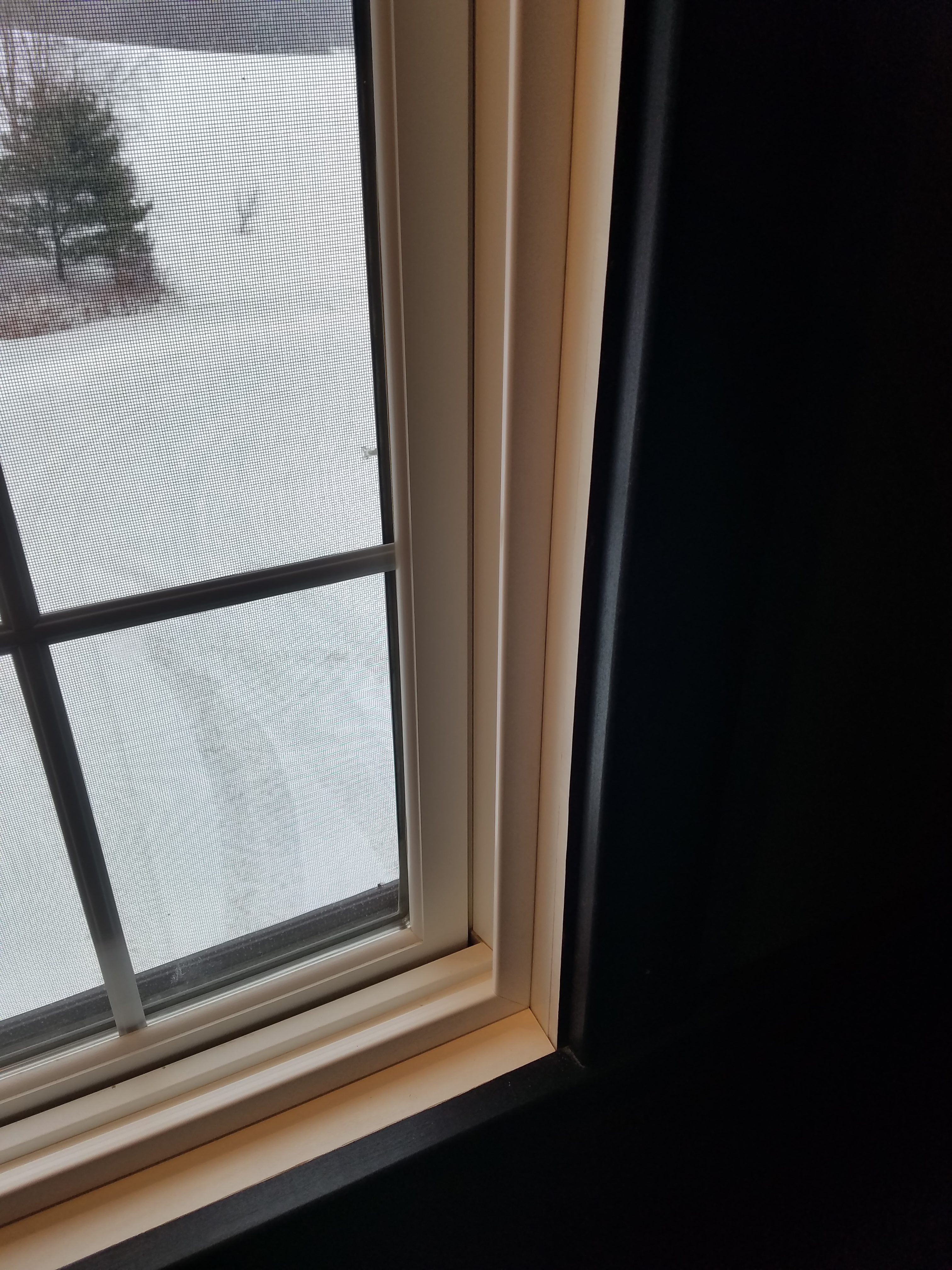
Trim
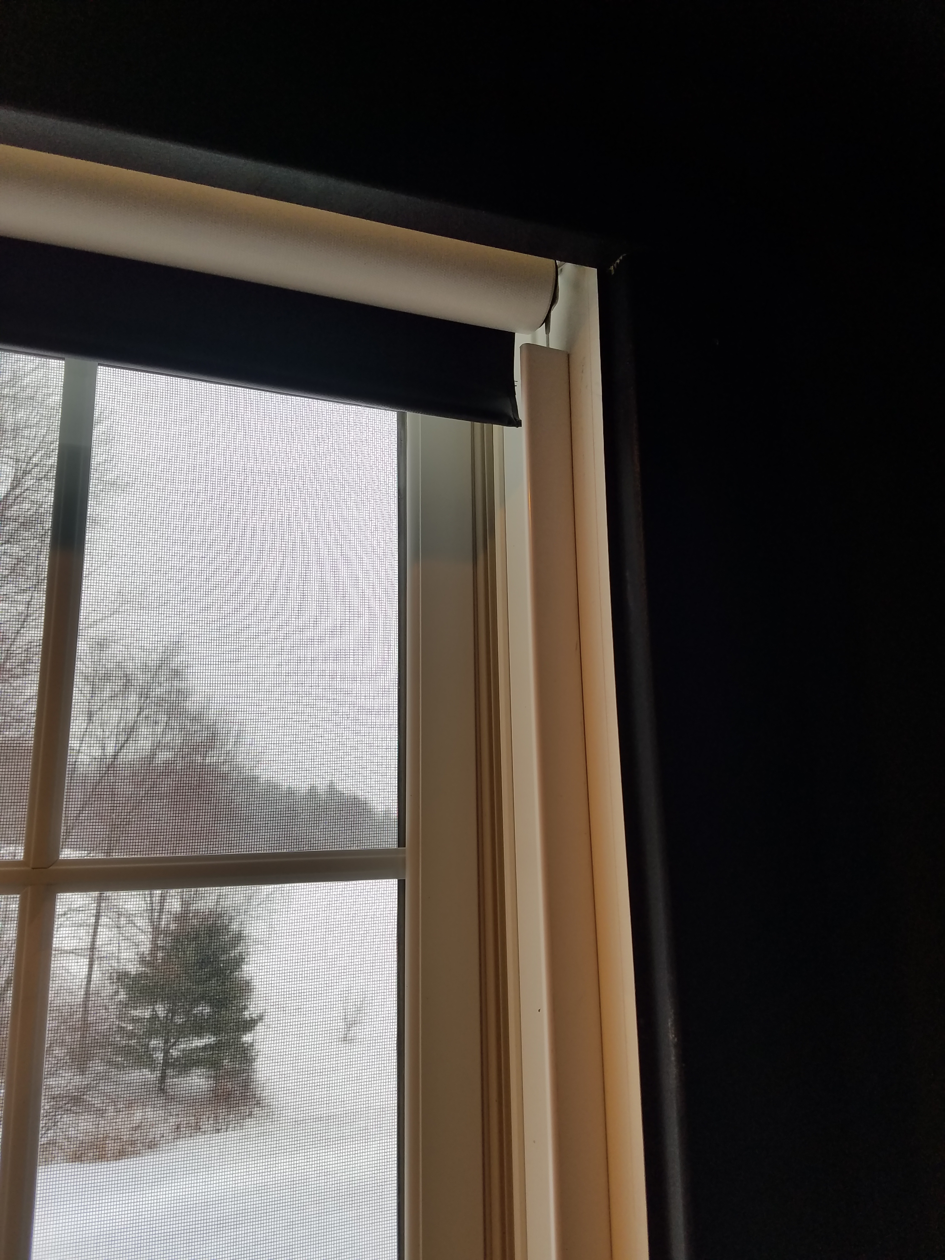
Trim
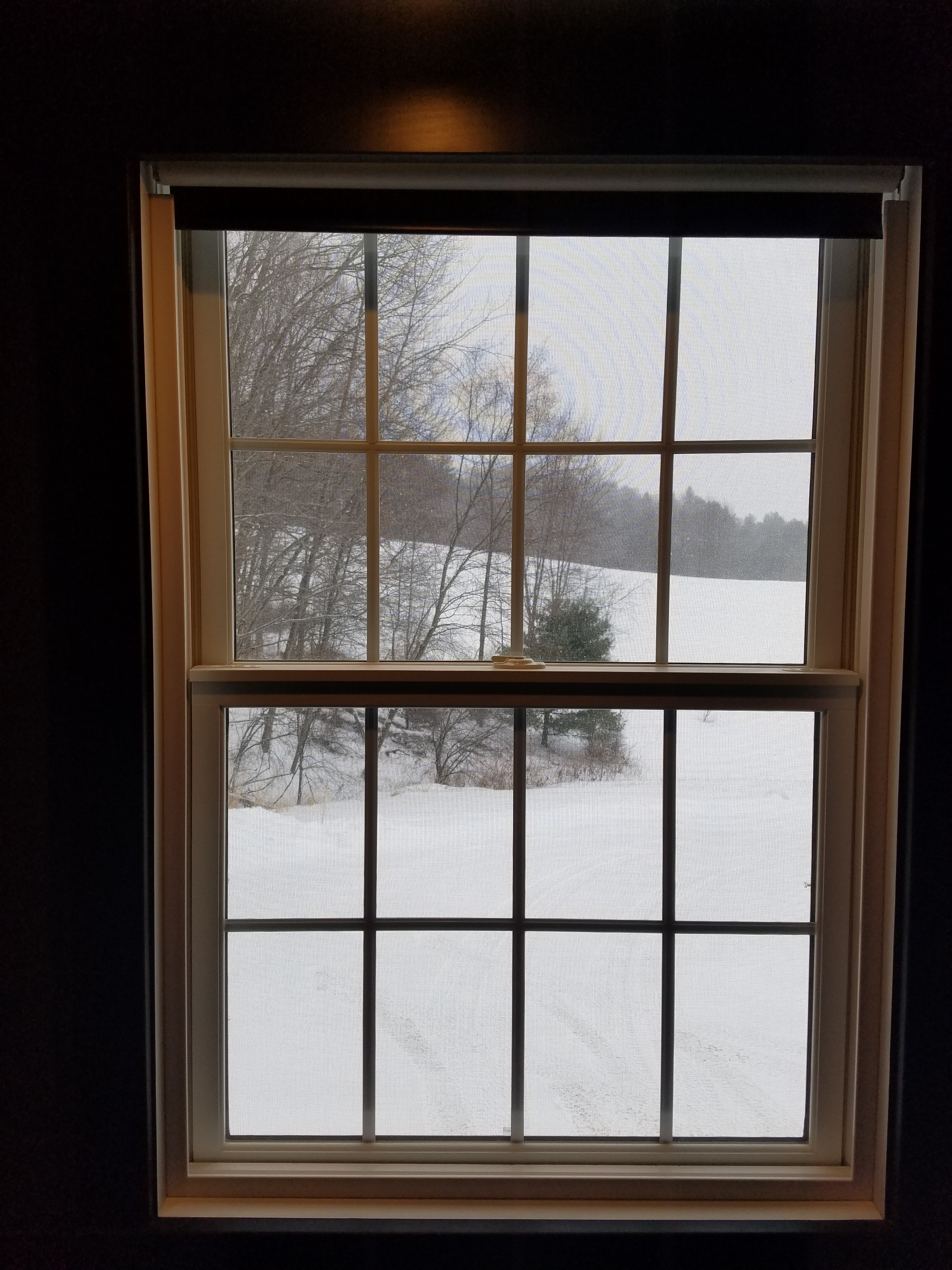
Blind Open
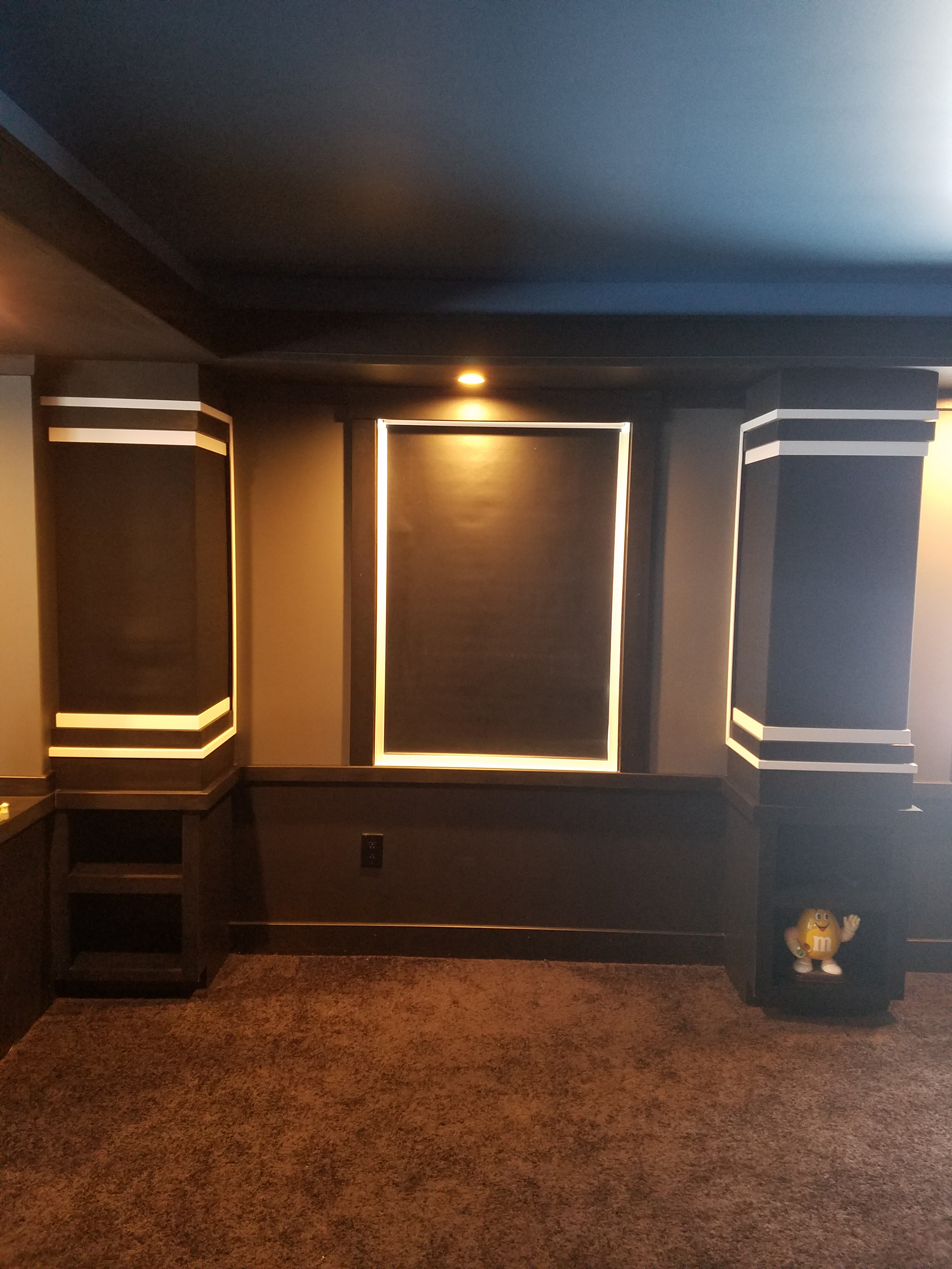
Blind Closed
Notice that you can't see the blind brackets. When I installed the top trim, I made it a little bigger than normal, so that it would cover them.
Wiring
I ran 18/2 thermostat wire from my home theaters wiring closet to each window. You should run them to an area where you will be able to conceal the wiring and that has power available.
Use the 12 volt power jacks to connect the thermostat wire to the blind motor wire. Use the male connector on one end and the female on the other. This will allow the blinds to be removed easily if needed.
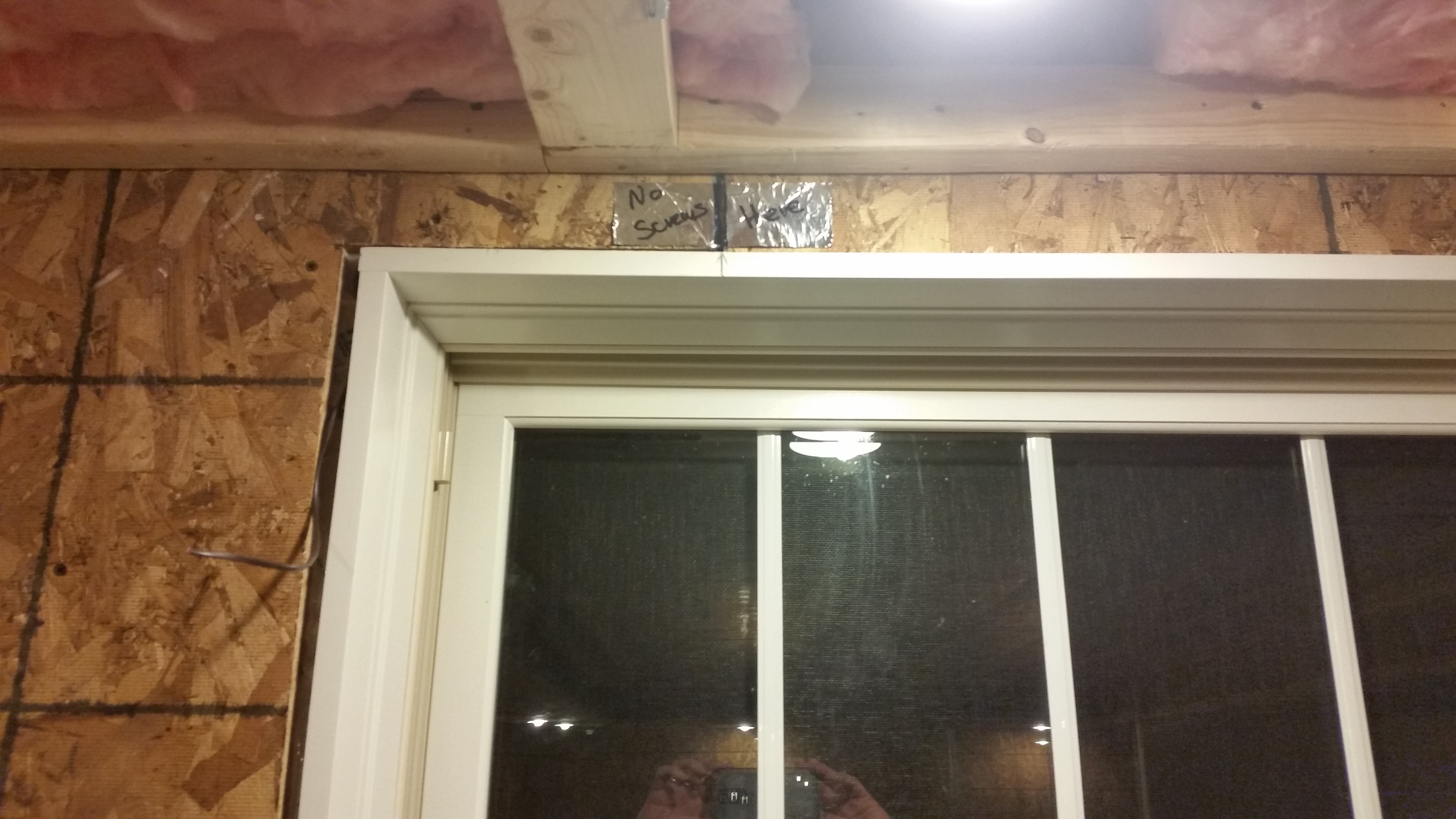
Rough Wiring

Blind Wire
I was able to get the connectors out of the way by tucking them up into a channel at the top of the window.
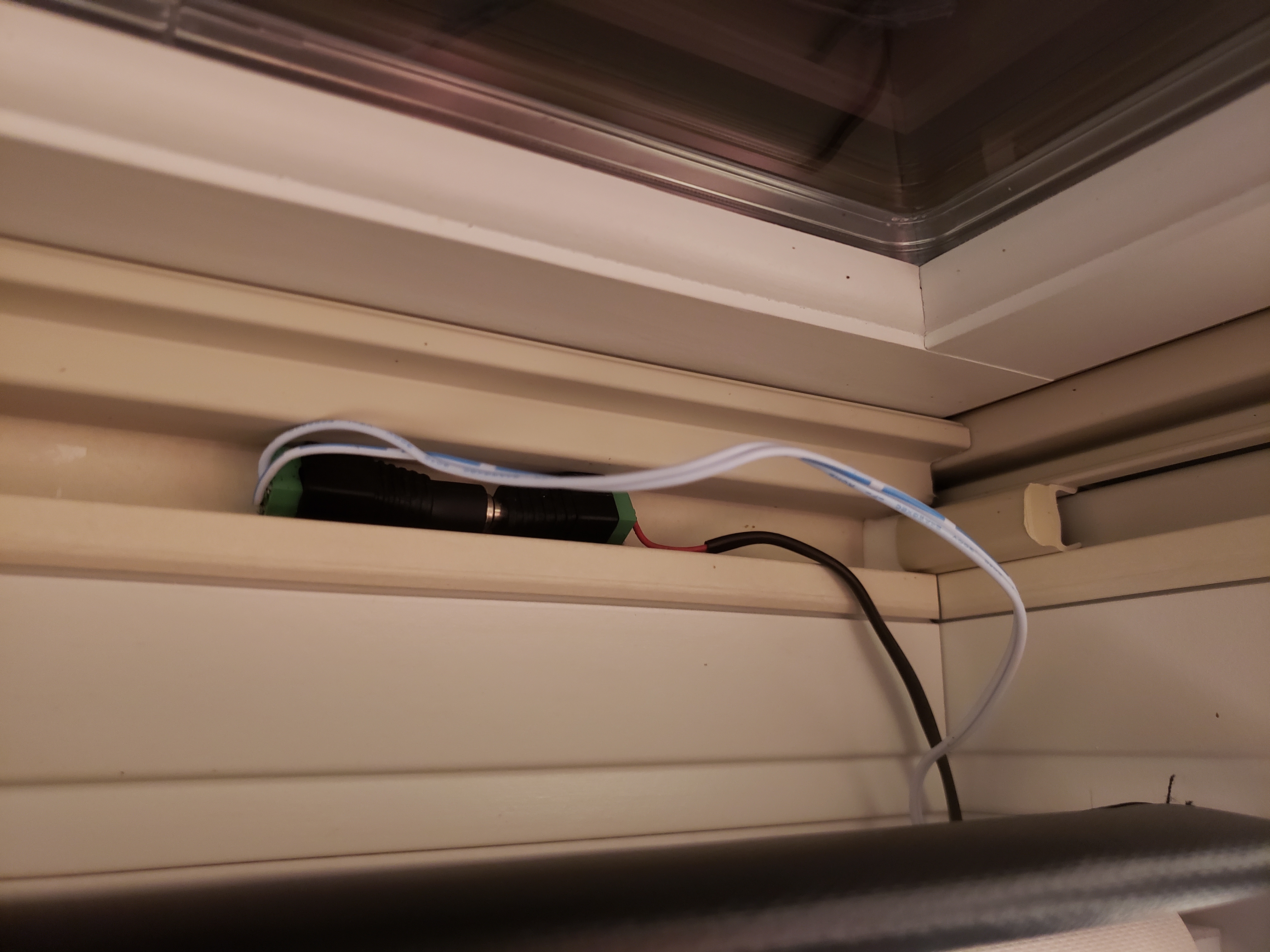
Connectors
The wires were run into a Leviton media cabinet and onto terminal blocks. The power supply I use is seen in this picture too.
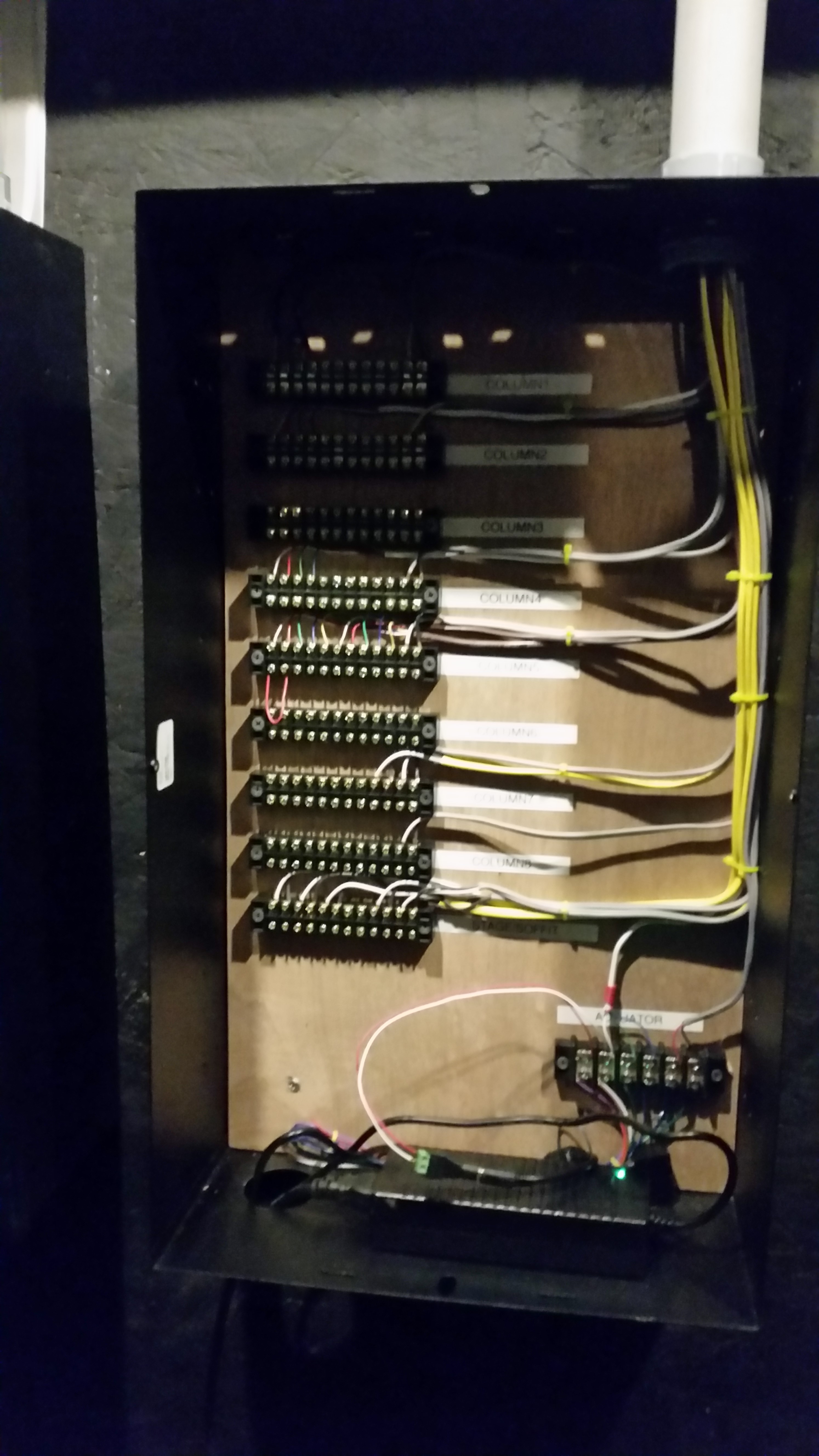
Wiring Closet
Wire the motors using the two Insteon 2450's and the reversing motor control as described below.
Make sure the MODE switch gets set to momentary by moving the jumper.
The motors should get wired into the motor terminals and the power supply gets wired into the IN POWER terminals
The CONTROL pins are where you will be interfacing with the 2450's using the 5 pin ribbon cable.
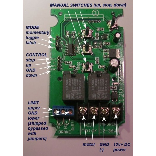
1 Ch. Blind Controller
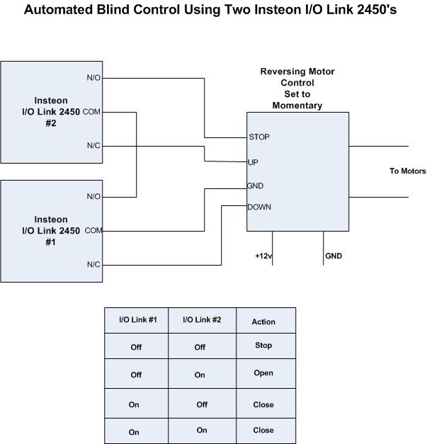
Insteon Blind Control Diagram
One end of the 5 pin ribbon cable plugs into the CONTROL pins on the controller. Cut the 5 pin connector off the other end and strip the wires, so they can be connected to the Insteon 2450s as show above.
If you have multiple blinds, get a terminal block like this to connect all of the motors to the controller. Just make sure you aren't going over the amperage rating.
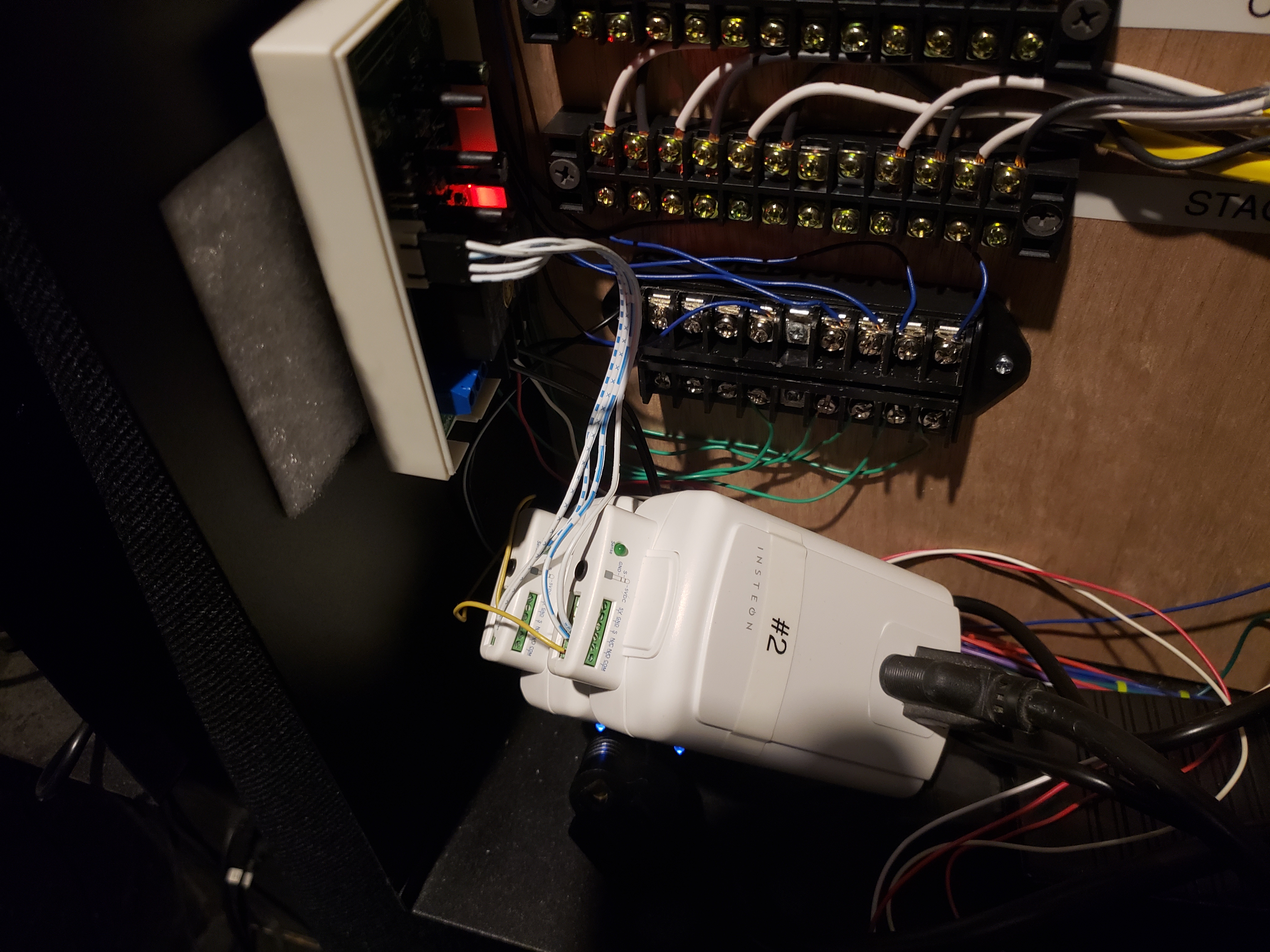
Blind Control
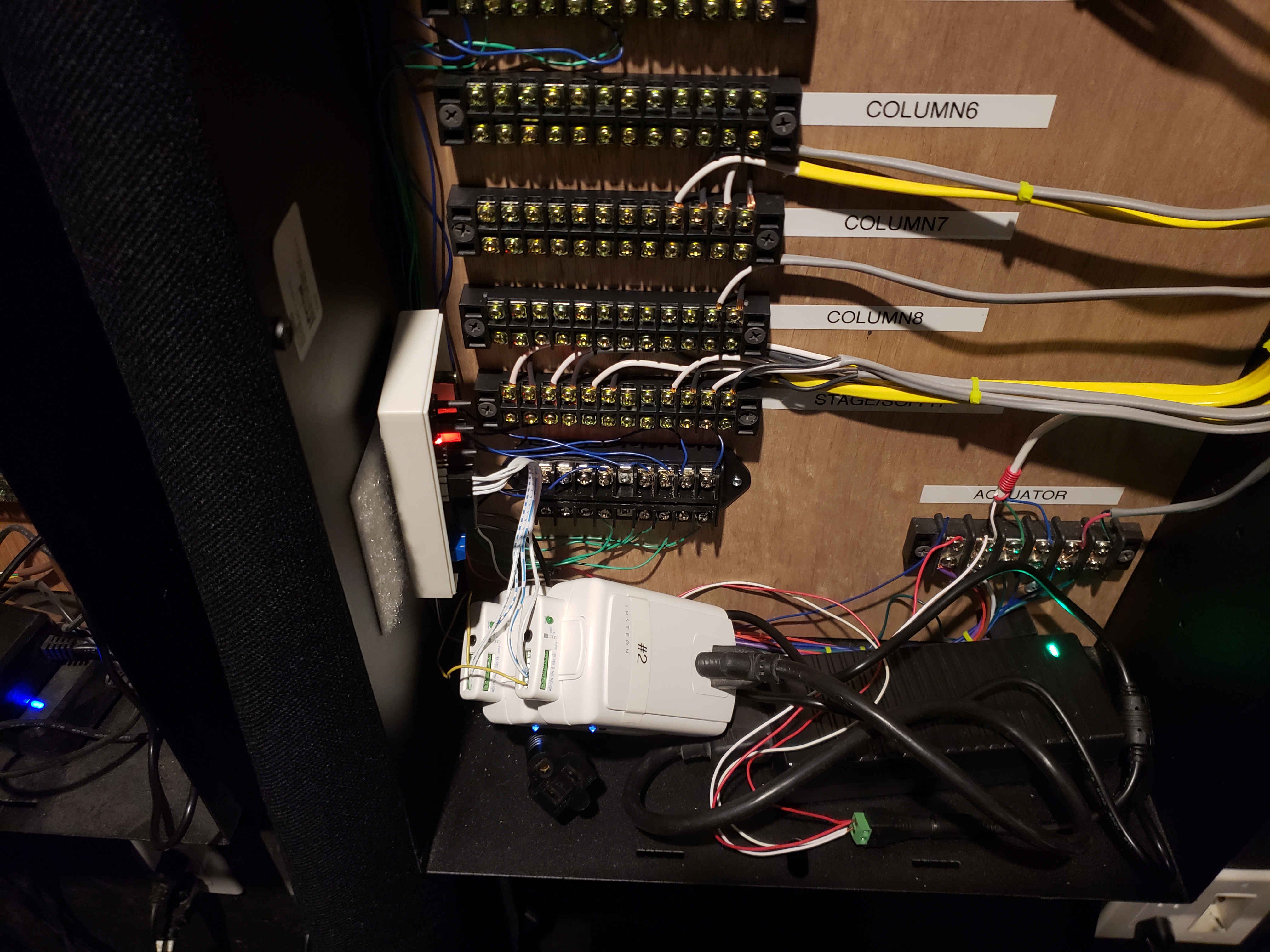
Blind Control
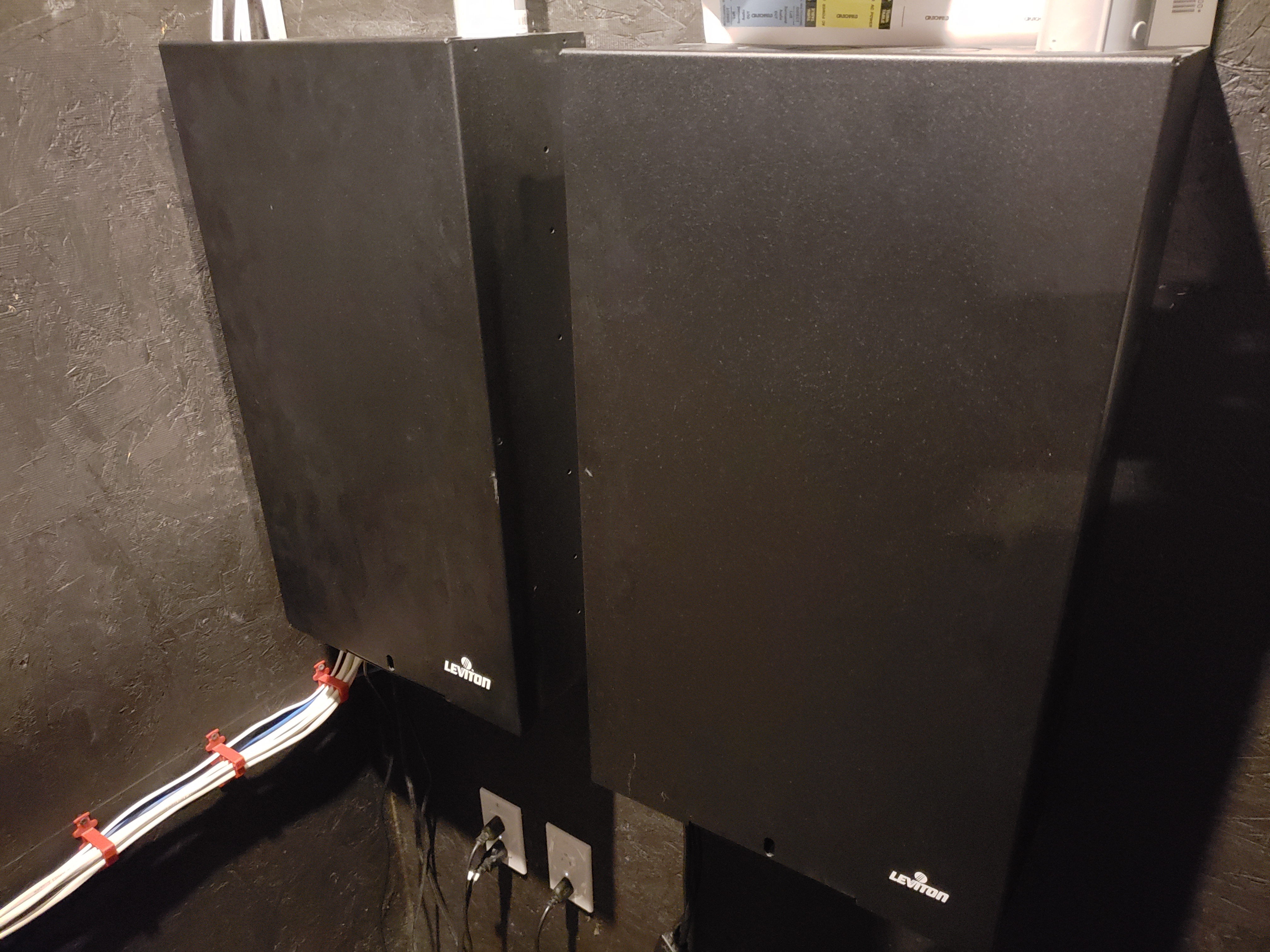
Media Cabinets
Programming the controller
I use an ISY 944i home automation controller. Below are the programs I wrote to open and close the blinds with the Insteon 2450s.
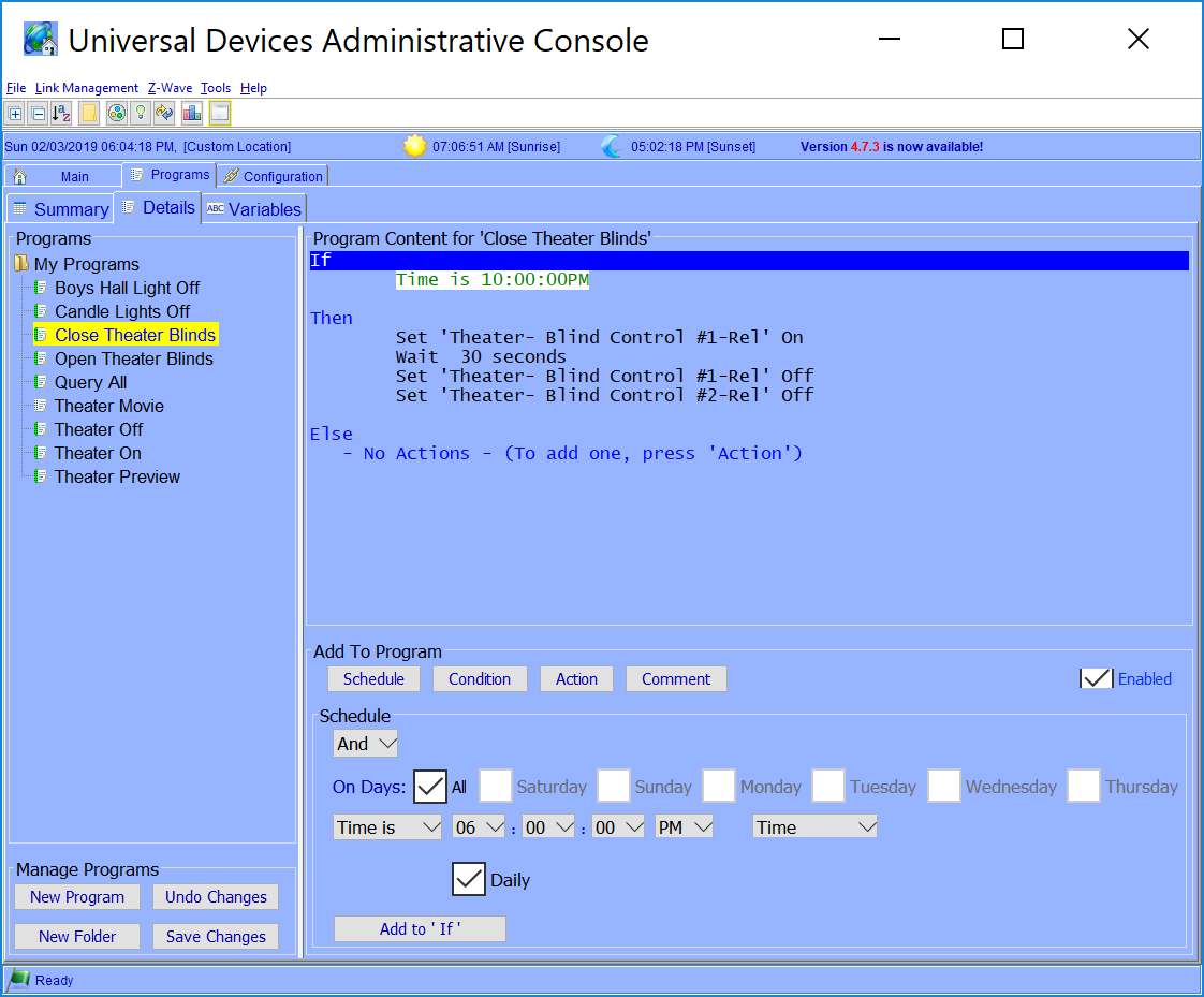
ISY Blind Close Program
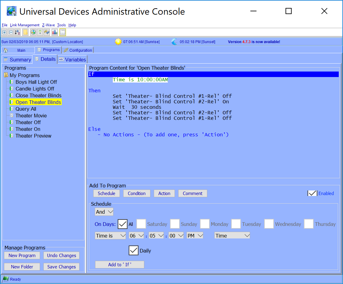
ISY Blind Open Program
Conclusion
Phew... That was a lot. It's difficult to get it all into one blog post. Installing your own motorized blinds will save you a lot of money. I hope this document helps you to do that. If you have any questions, please feel free to leave it in the comments and I will do my best to answers them.

